Most recent activity
-

Update on the Junior Ordinary restoration, final four lengths of 3mm X 500mm bright steel bar arrived today so it was an hour in the shed making the spokes,first heat up end of steel to glowing,put home made die over the bar and clamp in the vice,whilst still hot start to form a rivet head on the end of the steel to the same diameter of the die,next,cut the bar to the correct length (402mm) and put a chamfer on the blank end using a small file,once again clamp steel in the vice with about 3/4 cm sticking out of the vice,start to cut the thread using a 5BA die,cut thread to 1/1.5 cm,spoke made,I have attached a few pictures that might be able to explain it better than me
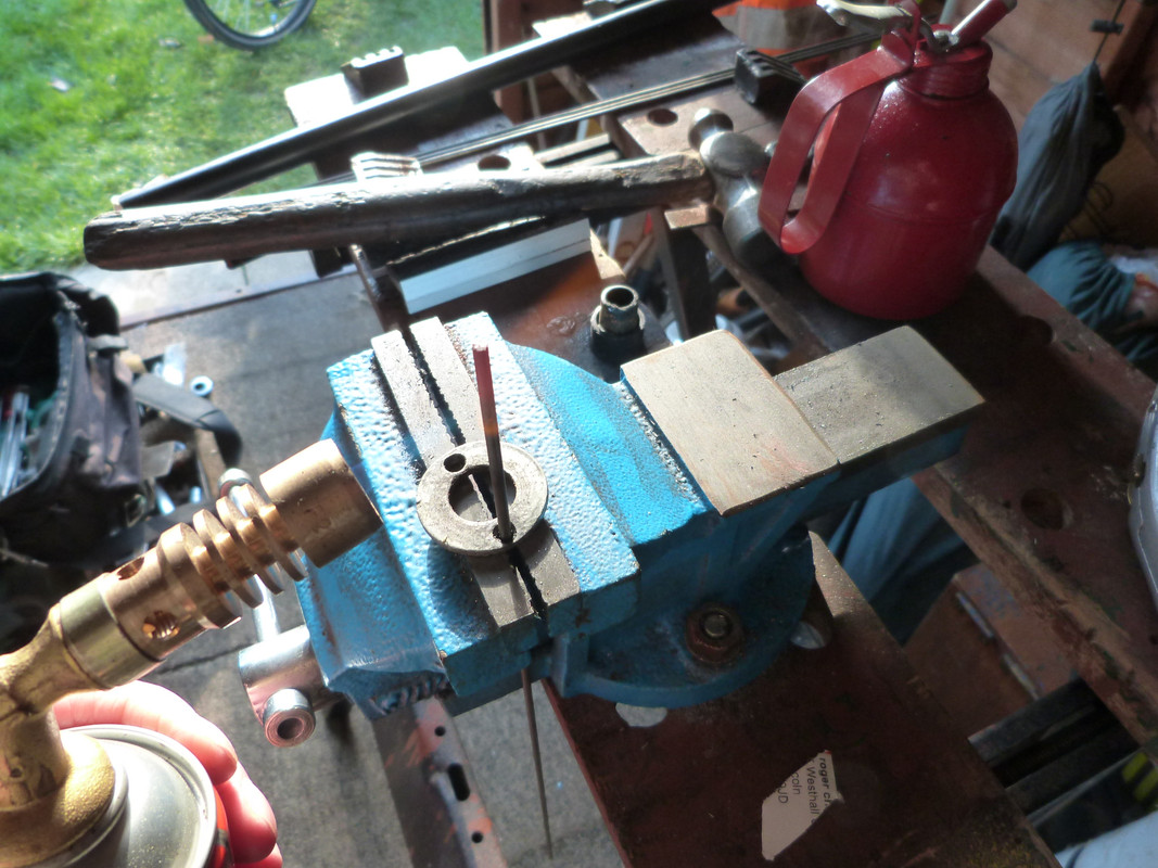 Heating the end of the bar
 Riveting the heated end with a ball pein hammer to correct size in the home made die
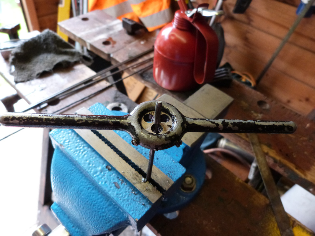 Cutting the thread using 5 BA die
 -

Thanks for the comments,they are appreciated.Not sure yet about the saddle but probably look for an old beat up leather job that requires a bit of work, (never done any leather work before) the problem will be how to mount it on the thin (approx 2mm X 40mm) strip of steel that was and still is originally fitted to the bike,might look at bending some round steel bar with a flat steel bracket either end to bolt to the frame using existing hole,the saddle should be easier to mount to that using a more conventional saddle clamp,will keep you posted when I've worked it out
-
-

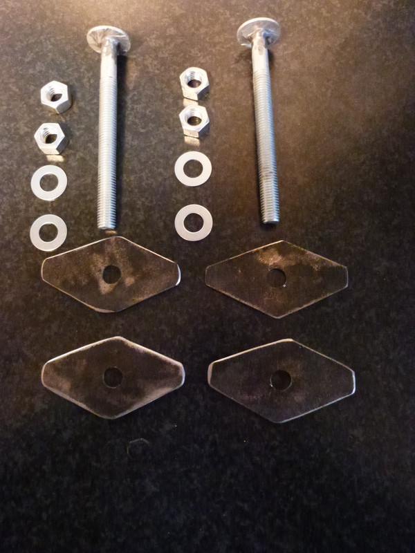
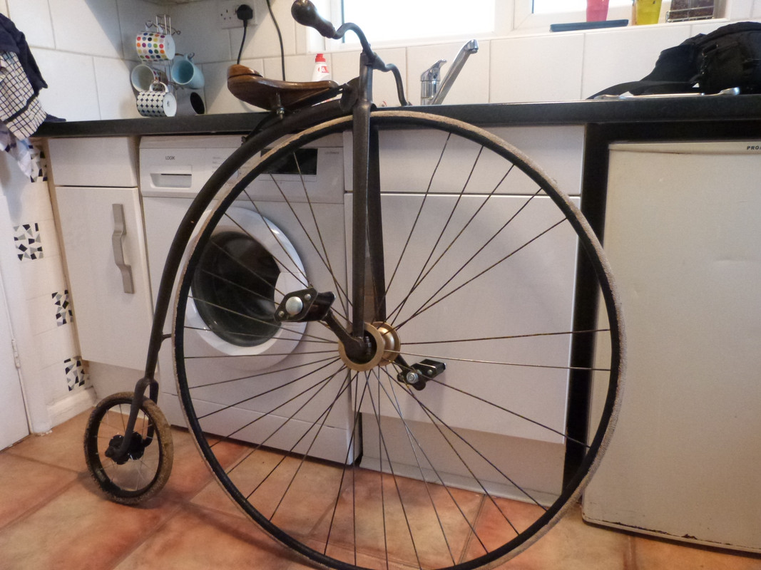
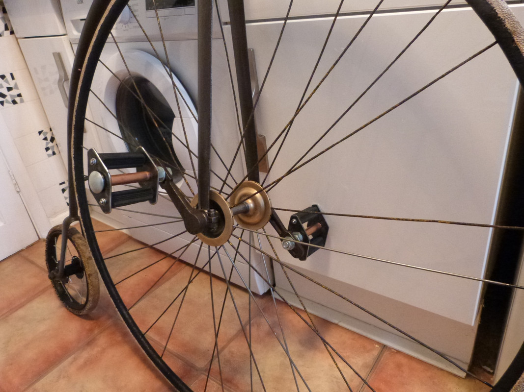
Quick update on the Ordinary restoration,End plates made for the pedals,I used some 3mmX50mm flat bar,shaped to a "Rhombus"(flat diamond),12mm hole drilled in the middle to take the axle which will be made from a 12mmX130mm coach bolts (these give a nice domed head) a brass sleeve will be placed between the plates on the axle to form a bearing surface,I have ordered a set of (four) pedal rubbers, two per pedal, these will be fitted to the ends of the plates either side of the axle then the pedals will be fitted to the crank arms

-
-
-
-

This is a picture of the steering head adjuster

With the adjuster/locking nut removed to show the top cone shape on the end of the main frame,this part fits into the steering head,there is a cone shape at the bottom as well

This picture shows the head end of the main frame that enters the steering head,as you can see there is the cone shapes at each end and these sit in corresponding cones in the head,slack is taken out by turning the adjuster on top of the handle bar and locking it off with the lock nut

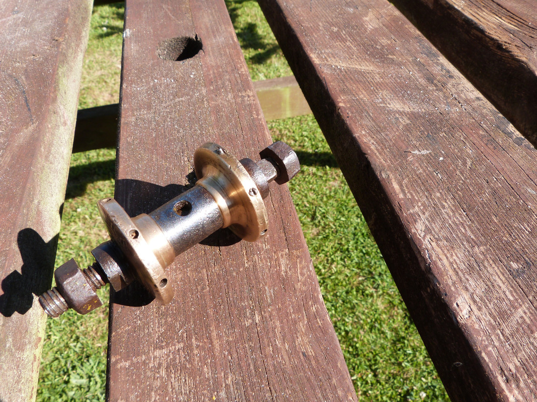
The rear hub works on the same principle,cones inside the hub and mating cones on the axle,as you can see from this picture there was a couple of broken spokes still in the brass hub,they created a bit of head scratching to get out but managed it in the end,this is a lovely bit of craftsmanship,sweating the brass outers onto a steel hollow shaft
-
-
.jpg)

Retired from working in the quarrying industry for most of my life, growing old disgracefully now and enjoying life