-
• #102
You're only dainty and rear brakes are basically optional anyway
-
• #103
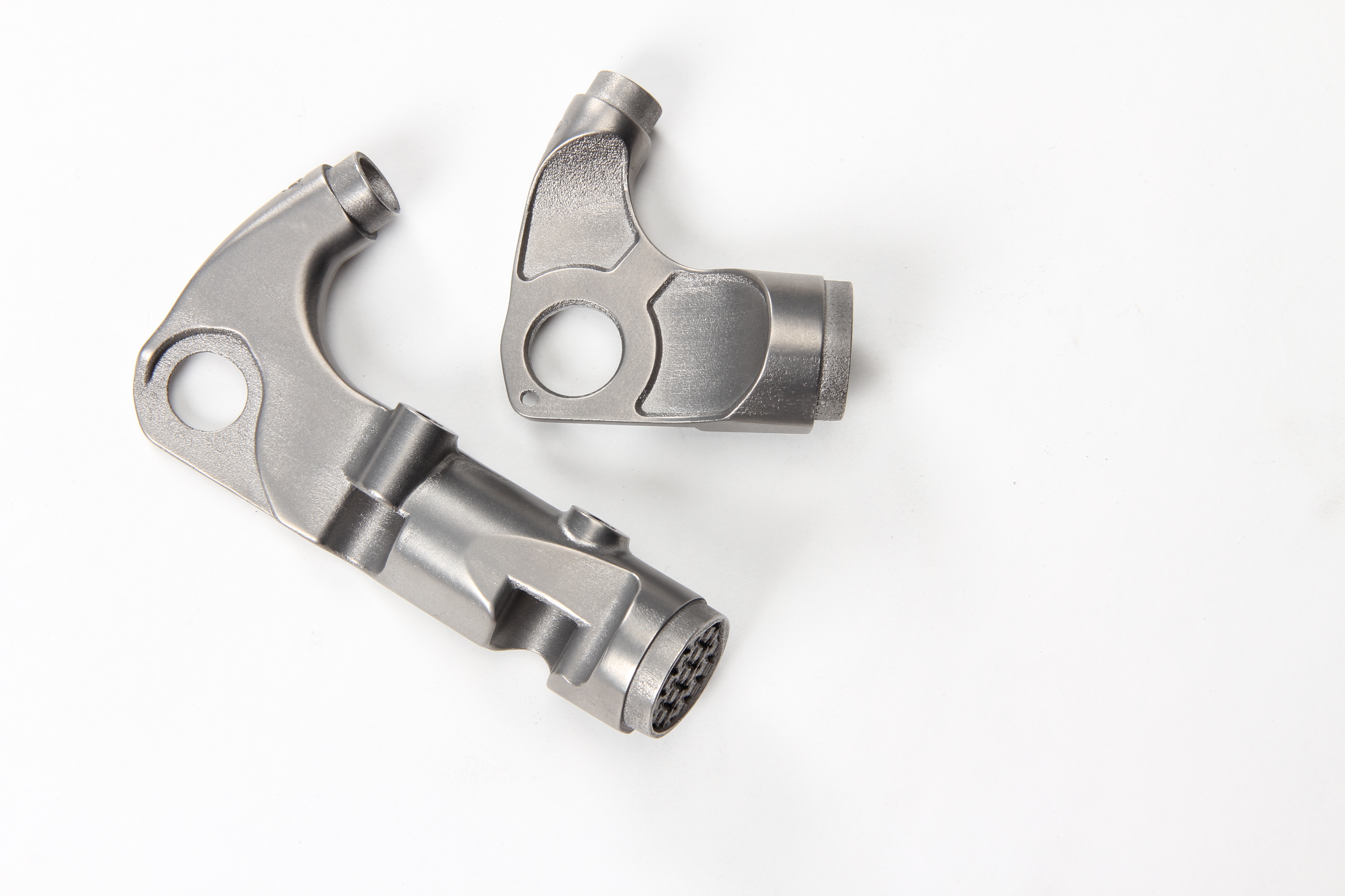
I think that with small pieces like these hollow walls aren't really the point. This is more a case of being able to make complex geometry to exact dimensions. If you look at the mounts @ectoplasmosis had welded on they work because everything is in the same plane. But with my boost spacing frame and post mount brakes you'd need some pretty funky bends.
I think the three uncertainties in having those brake bosses printed are.
- Will they survive? And if not how fucked is the frame?
- Did I accurately draw the tubes in CAD? I'm going off some pretty dodgy drawings, and I'm not even sure that the drawings match the tubes that come out of the factory.
- Will Phil be able to accurately recreate my CAD drawings? I think the world of him, but this would require sub millimeter precision. And even if it's perfectly tacked, the tubes warp during brazing and what not. Although I would of course add a bit of thickness for some leeway, but more leeway would also mean more filing.

- Will they survive? And if not how fucked is the frame?
-
• #104
Is there any shrinkage with printed metal like there is with plastics?
-
• #105
I believe the problem is warping rather than shrinking. A Mech Eng PhD friend of mine worked on algorithms to compensate for it.
However, going by the Shapeways support forum it’s mainly a problem with large and thin parts.
-
• #106
For metal printing the workflow is proprietary - the "slicing" software is machine specific and the powder characteristics are controlled so shrinkage is accounted for in the machine.
A different story with steel printing apparently https://imaterialise.helpjuice.com/design-printing/shrinkage -
• #107
Got there before me!
In my experience of working with metal printed parts I noticed that part orientation with the powder bed seems to make a bit of a difference in dimensional accuracy -( I was making small rotating parts) -
• #108
Going back a couple of replies, don't forget when you design a part you should be thinking about how it should be made if it were 3D printed, not as if it were a machined part. The way you design it is almost always different. You want to be optimising the properties of the material and how it's made. Obviously, those parts were used to get an idea of cost, but never make the mistake of trying to replicate machined parts in a 3D printer - it's a missed opportunity to do the things you can't do when you start with a solid block!
-
• #109
Thanks for the @ and pointer to the existence of this thread.
Living vicariously through experiments with dork materials and processes gets me v moist.
-
• #110
Will Phil be able to accurately recreate my CAD drawings? I think the world of him, but this would require sub millimeter precision. And even if it's perfectly tacked, the tubes warp during brazing and what not.
This is why printed dropouts typically include the brake bosses too so that the alignment of both bosses and the axle is all done in the printer rather than on the welding jig

The reynolds dropout is eyewateringly expensive ($395 from Ticycles) but with a bit of thought you could create a self-jigging, self aligning disc mount that would eliminate this risk and allow for a standard dropout
Time for a dodgy sketch methinks
1 Attachment
-
• #111
and while we're on the subject of disc tab alignment and 3d printing I'll just leave this one here....
https://www.thingiverse.com/thing:3574514 -
• #113
Yes! I looked at doing a full dropout, but it gets both pricier and trickier. With the brake adapter I'd just print it solid and hope for the best, but with a full dropout you'd need to get into those lattice structures and making sure it's strong yet light. And then paying for somebody else's expertise gets even more expensive, as the Reynolds dropout shows.
The mounts on the previous page would in theory be self jigging as I had cut the tube facing faces 'to size', that combined with a disc brake alignment tool should be safe. This has become far more interesting now I've discovered a conventional mount wouldn't work with my current choice of seatstay and chainstay. The blue faces would need to touch a tube.
1 Attachment
-
• #114
Hmm the plot thickens
Like @Jonny69 indicated, you could be looking at a design for AM challenge here... The printed part could be literally any shape you can model.. I’d be inclined to put a couple of M6 thread inserts into the locations dictated by the caliper so they’re hovering in free space and then work out the most efficient way to tether them to the frame -
• #115
Is that fusion360?
-
• #116
The most efficient way would be using an IS mount with a PM adapter. But it's not necessarily the most fun way.
1 Attachment
-
• #117
Yes, I really rate it. Coming from Siemens NX I sometimes need 4 features to do what I used to do with a single feature, so there has been a learning curve. But now I've gotten used to it, it's perfectly adequate. And the license not costing roughly a Bastion frame per year is a big plus now I no longer have my uni license.
-
• #118
Bastion frame per year
I cant wait to leave uni, but this is my one fear - Not free software.
What is life without solidworks?
-
• #119
This.
in 2017 I managed to blag a years worth of license from solidworks through some entrepreneurs deal and last year I got a years license of Altair on the basis that my team were looking to integrate it into some topology optimisation software but blagging proper CAD licenses is hard work when you're not a student
I guess you can keep changing email addresses to claim free Fusion360 (if the free year deal is still a thing) -
• #120
This instructable is mildly amusing but an interesting hybrid process involving AM
1) FDM print lugs

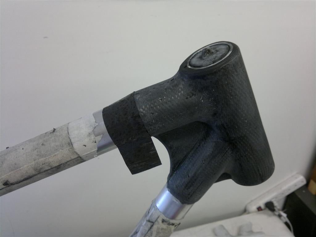
2) cut tubes (alu, steel, carbon etc) and bond them into the printed lugs
3) print moulds for the lugs and lay up the carbon mats

4) demould and tidy the lugs

-
• #121
The lug workflow is similar to one I used a few years back to create leg braces.
2 Attachments
-
• #122
Awesome i like that idea. Ive been toying with the idea of experimenting with some composites on non structural stuff. Never really got round to getting it done, but i feel like there's alot of scope for cool stuff.
-
• #123
https://www.instagram.com/project_d_bicycles/ theres this person doing some fun stuff with 3d printing and carbon
-
• #124
There is or was a guy in the UK making MTB frames like that but without a mould, I think just wrapping a 3d print then vaccum bag and dissolve the plastic.
Edit: found him:
https://bicycledesign.net/2015/01/3d-printed-mountain-bikes-by-adrian-smith/ -
• #125
Thanks for the link - this is excellent work
 PhilDAS
 Tijmen
 sohi
sohi Rik_Van_Looy
 Jonny69
 ectoplasmosis


 Biggles567
Does that shape make sense as a 3d printed piece? Are the walls hollow?