-
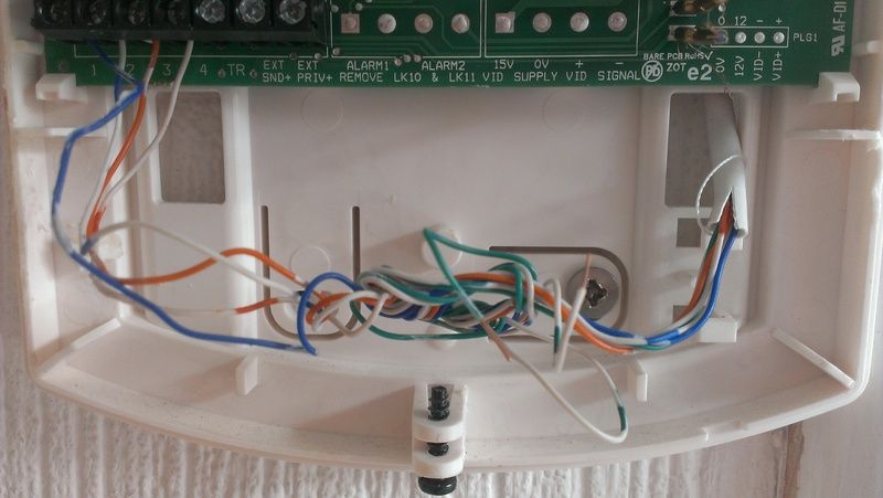
this is the existing unit, which i believe this document pertains to (useful!)
this is a close up of the bundle of wires which seem irrelevant:

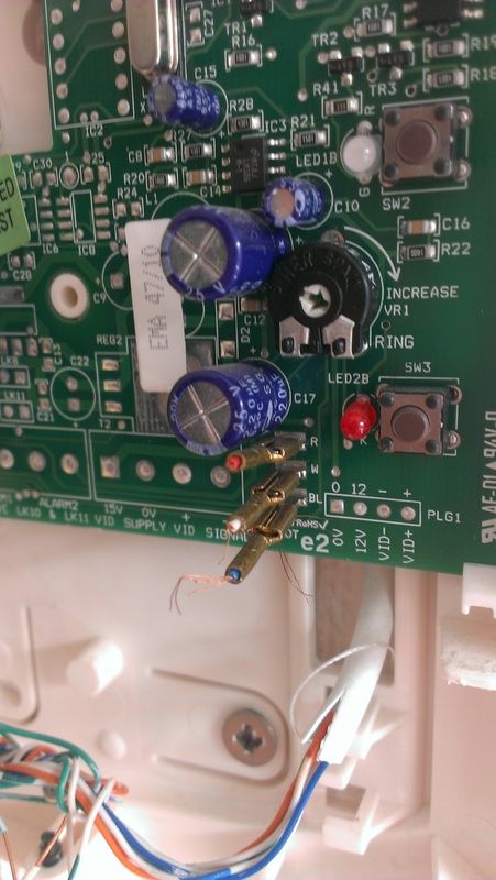
and a closer look at the b/r/w wire endings which were severed:

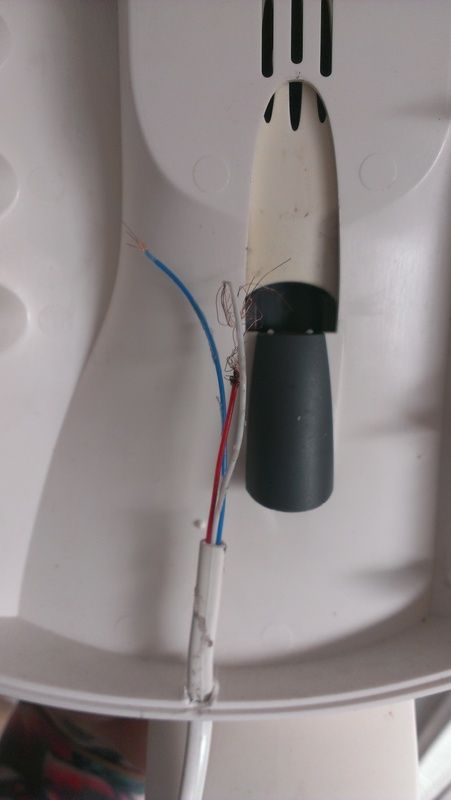
from the corresponding wires on the outer part of the handset which comes away:

from the instructions of the booklet i found (link above) it looks like i just need to reconnect the b/r/w wires?
-
ah, some fucker pulled the handset off!

the unit is powered by -50V from the striped telephone wires - so don't disturb those.
it's a case of replacing the crimped ends [spares and crimp tool easily found in places like Halfords] on the handset cable then removing the severed ends that are still attached to the circuit board and plugging in the new crimped cables - when you do this bit wear some marigold gloves as you don't want to be touching the blue cylinders (capacitors), and causing problems on the circuit board. A pair of needle nose / radio pliers would be handy for this step.
In summary, you wouldn't be harmed by working on this, from the supplied document each handset is on a separate set of terminals so unlikely to disrupt the other tenants if it stops working. But if it stops working you may need to replace the whole assembly, so take care.
-
Yeah, just replace the connectors. Make sure that you get connectors that will fit the wires and the spade connectors on the board. Also a decent crimping tool to do the crimping, i use a bit of leaded solder as I have had years of poor crimping tools and having to double up to get a good join.
Also careful when removing the connectors as pulling them out might damage the spade connector on the board. A trick can be to lift the tab on the connector
 ioreka
 rive_gauche
 rodabod
 lynx
lynx
what's wrong with the existing unit, and are there any model/part numbers?
how many white cables go into the unit?
A piccy of the places where the existing wires are terminated would also help